Posted on

Replacing the chip in your BMW

TRM Tuning OBD1 Chip on Circuit Board 01

This document will need photos for each step.

While this article will focus primarily on the Motronic 3.3.1 system in the E36, the general information will apply to many other similar systems. The engine computer is often referred to as the ECU or the DME.

The ECU is located in a cubbyhole behind the right side shock tower in the engine bay. In stock form there are both an acoustic cover and a weather tight cover that seal the compartment.

The acoustic cover is held on with 3 push clips in its midline, and a few 10mm large plastic nuts at the base.

Only the push clips are required to be removed. Using a small screwdriver, pry back the center pin and the rest of the fastener will easily be removed. Do this for all three clips.

With the acoustic cover removed, the 4 Phillips head screws will be visible. Unscrew these but do not pull them out of the cover.

With the screws undone, you will be able to pull the top of the cover towards the front of the car, and then pull up. The bottom of that cover/door fits into a slot on the chassis.

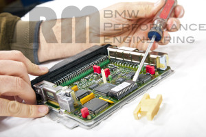
With the door removed, the DME is now exposed. To remove it, simply slide it forward. It is held in with spring locks, so there will be some friction/resistance.

With the DME out of the compartment, remove the plug. To unlock the plug from the DME, pull the silver latch on the top of the plug away from the DME.

With the DME out of the car, set it on your clean dry workbench.

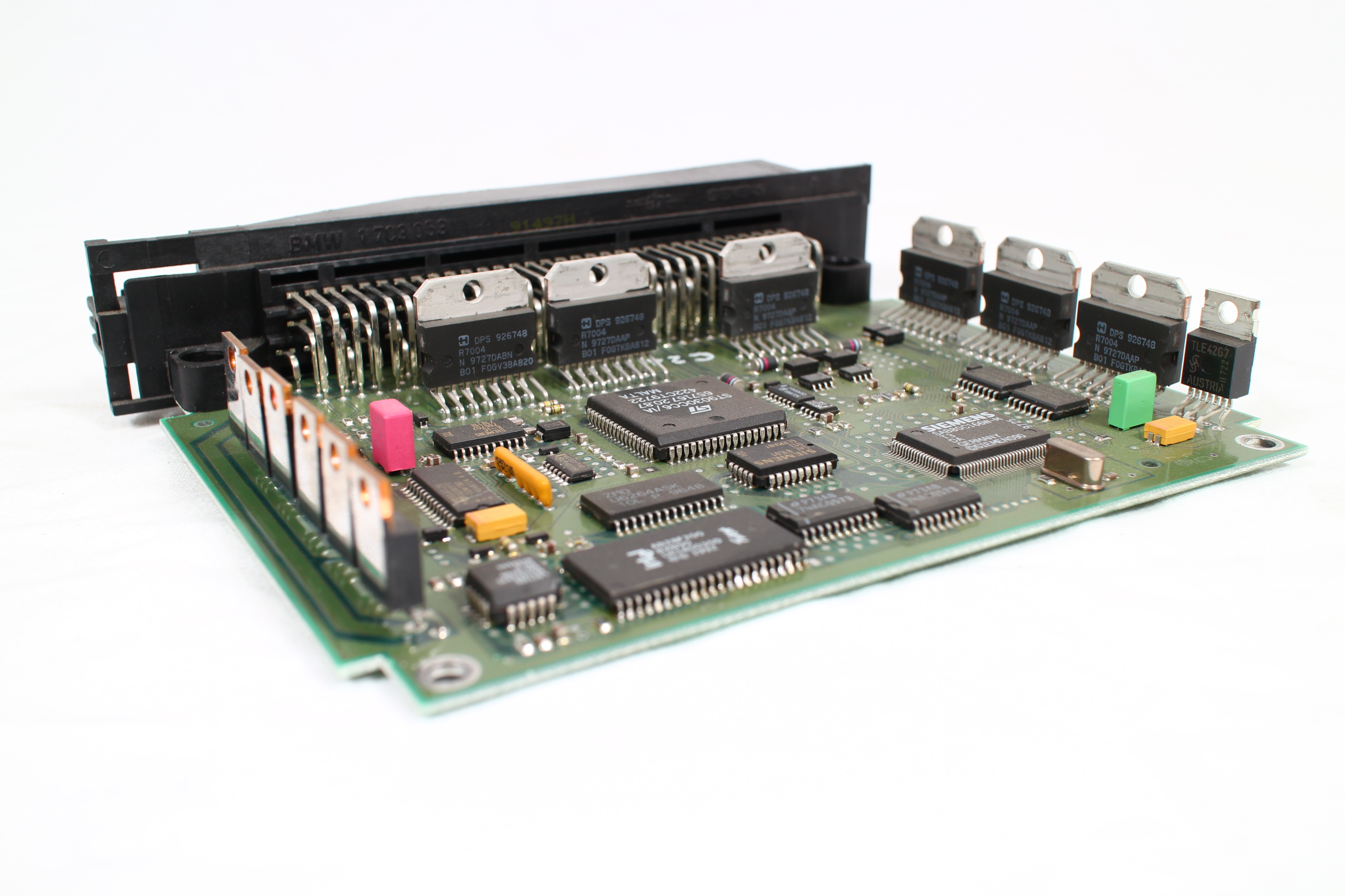
Remove the cover. (bend lock tabs. remove torx screws if so equipped.)

TRM Tuning OBD1 Chip Install 01

Remove the chip cover/lock.

TRM Tuning OBD1 Chip Install 02

Remove the chip. (If this ECU already has a chip, make sure you remove all of whatever was there, including any aftermarket daughter boards.)

TRM Tuning OBD1 Chip Install 06

See photo for “Daughter Board / Encryption Board” – Note extra circuit board above chip socket.

TRM Tuning OBD1 Chip Install 09

Many customers will not have access to a “Chip Puller”. If you are using a prying device work the chip up from each end slowly.

TRM Tuning OBD1 Chip Install 04

TRM Tuning OBD1 Chip Install 05

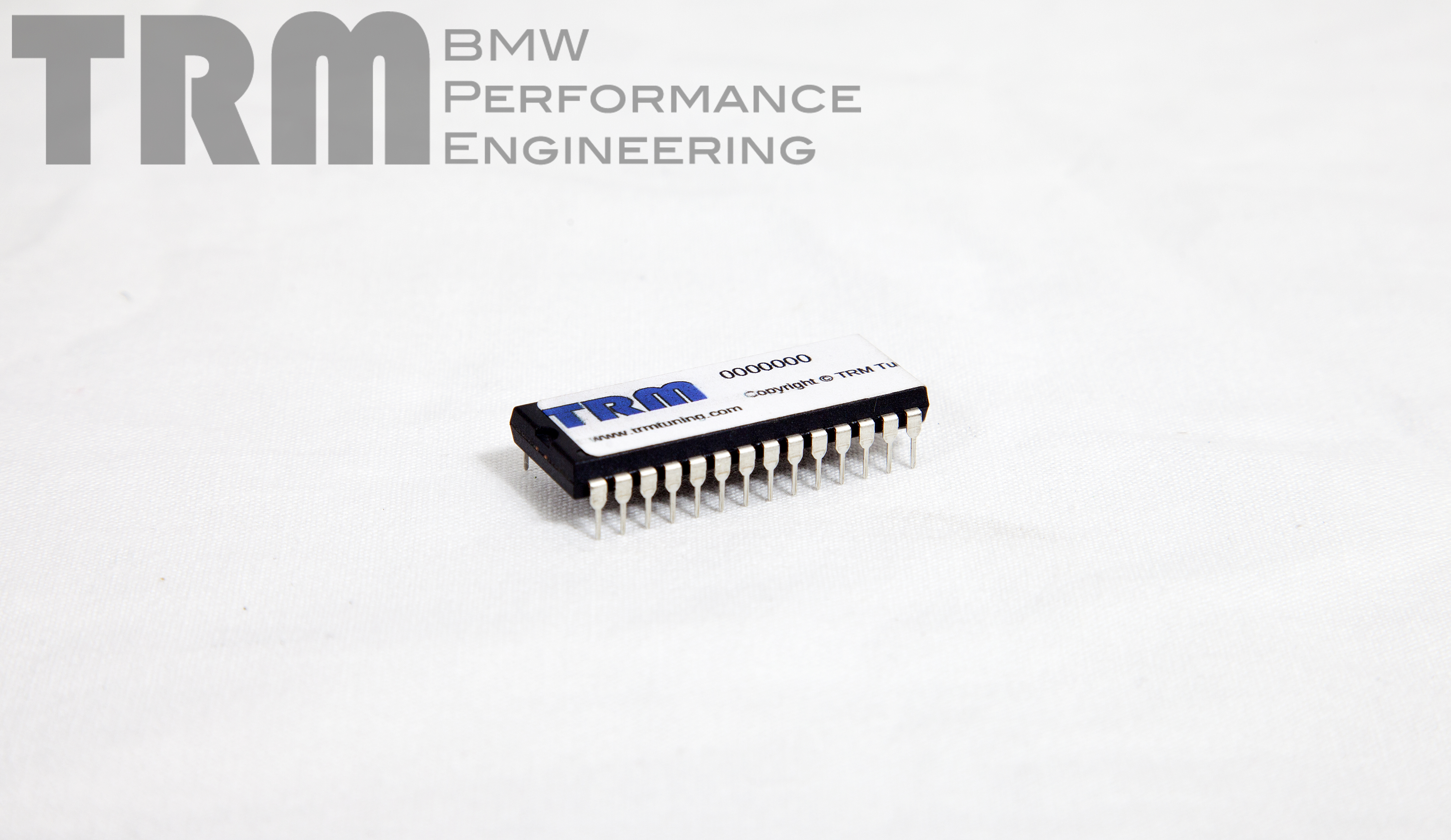
Install the TRM chip. Make sure to align the notch on the end of the chip with the notch on the end of the socket.

TRM Tuning OBD1 Chip on Circuit Board 01

Replace the chip lock/cover.

TRM Tuning OBD1 Chip Install 01

Replace the ECU cover.

Plug ECU into harness.

Slide ECU back into compartment.

Replace the plastic cover making sure to properly seat the harness in the cover before screwing it down.

Replace the sound cover.

Posted on

EWS on the E36 chassis

TRM Tuning OBD1 Chip on Circuit Board 01

What is EWS? EWS is “Elektronische Wegfahr Sperre”.

Don’t speak German? Then that probably wasn’t helpful. EWS is BMW’s electronic drive away protection system.

The exact implementation of EWS on the E36 varied slightly through the years, but the general lack of long term reliability stayed the same. Key failures, antenna failures, and module failures are not as uncommon as they should be. The system can also present problems when doing motor swaps.

For this reason, all of our OBD1 performance chips for the 413/506 are EWS delete chips. We also offer a separate EWS delete only chip that only disables EWS.

For OBD2 equipped vehicles, or for swapping an OBD2 motor into an earlier car, we also offer EWS delete options for the MS41 based E36’s.

EWS delete in the ECU only removes part of the system.

TRM Tuning OBD1 Chip 02On OBD1 cars, if the chassis was equipped with EWS, you need to remove that link between the EWS computer and the DME as well as use an EWS delete chip. The wiring can be disconnected at the DME side (pin 66) or at the X20 side (pin 7). The X20 is the easiest to access and cleanly modify.

We recommend pushing the pin out of the X20. (big round plug by the fuse box.) If you unscrew that connector, pull back the boot, find pin 7 (green wire), twist the lock mechanism on the connector, push the pin (pin 7, green wire) out of the connector, re-lock the connector, fold the pin/wire back into the boot, put the boot back on, and reconnect the connector.

For EWSII equipped cars, there is also a starter lockout. We recommend bypassing that as well. On the EWSII module itself, there are only two large wires. Those are the wires for the starter solenoid. Cut them near the plug and butt connector them together and your car will start even when the key transmitter or antenna fails.

Posted on

Oil quality and the life of your car

IMG_8118

Engine oil gets contaminated over time by moisture, fuel, and particulate matter.

Moisture generally being introduced as a byproduct of combustion, it is easily burned off by getting the oil up to temp. If you have a short commute, it is a good idea to take a long drive at least once a month in an effort to get the oil to a more reasonable temperature.

IMG_8121Fuel contamination is generally a result of cold starts. We generally gauge the life of the oil and the change interval based on mileage, but most of the degradation and contamination of the oil with short commute vehicles is a function of cold starts. It is best to crank the car and start driving immediately. This will cut down on the warm-up time and reduce the total contamination from the cold start event.

Particulate matter in the oil gets there one of two ways. The first is via the air filter. The air needs to be as clean as possible going into the engine. The fine particulate can cause engine wear. The oil filter will catch a lot of it eventually, but that may be after it has spent some time on the side of the cylinders causing wear. We recommend either paper filters or multi-layer foam such as is found in our intake kit. The other particulate matter in the oil is generally a function of the wear. This will be ring material, cylinder material, and possibly bearing material. Some wear is normal over time, especially on cold starts when the parts of the engine are not their ideal shape or size. Catching some of that wearing material before it gets run through the oil pump can help reduce some of the secondary effects, so a magnetic oil drain plug is a good idea.

An appropriate oil change interval with a suitable oil will be the best way to prolong the life of your engine. Not every application is the same, so it is a good idea to consult with experts regarding your particular needs. Collecting an oil sample and sending it off for analysis is a great way to see if you need more (or less) frequent oil changes as well as keeping an eye on what is going on with your motor over time.


Posted on

Recommended chargers for flashing your BMW

When flashing new software to your car, it is important that the voltage be held constant. That stability will ensure there are no problems with writing the data to the very sensitive ECU. Any fluctuations in voltage can cause a “bad write”, and as a worst case, “brick” the ECU.

Voltage drops can be caused by a number of seemingly insignificant things. Opening a door or trunk during a flash can turn on the dome lights, or trigger other chassis functions, which can cause a voltage drop. A heat soaked radiator can trigger the Aux fan to turn on causing a voltage drop. While not all of the possible causes can be prevented, a strong charger can mitigate the possible bad outcomes.

We recommend the following chargers when using the TRM flasher:


Posted on

Ethanol and your fuel system

It is becoming common to blend Ethanol with Gasoline in many states. Most stop at 10%, but there have been cases where higher concentrations of Ethanol has been found in pump fuels.

Ethanol by itself is not bad. E85 (75-90% Ethanol, the rest Gasoline), if you have a readily available supply, can be great low cost high octane fuel.

The downside to ethanol, especially in low ratios such as E10, is that you do not get any of the benefit of ethanol’s high octane rating. You do get its cleaning properties though, and that is where the trouble begins. Ethanol will clean off the varnish and other deposits in your fuel tank and fuel system. Usually (hopefully) this is caught in the fuel filter. It is not uncommon for fuel filters to be come clogged very quickly as the switch to fuels containing ethanol is made. The good news is that this is not a perpetual case. The “dirty” stuff will be cleared out fairly quickly and it may only take killing a handful of filters before the change interval can return to normal.

The other potential problem is compatibility with the fuel system. Modern fuel systems should all take 10% ethanol fairly easily. It will speed up the deterioration of  older fuel lines, and it is always a good idea to replace all of the soft lines on the fuel system with some frequency.

E85 as a fuel is a lot harder on the fuel system than E10. You will need Viton or similarly chemical resistant fuel lines installed. You will also need a larger capacity fuel pump and larger injectors, as it will take approximately 30% more fuel to make the same power.

Posted on

Common Boost Leaks on Forced Induction M50-Series Engines

There are a number of common problem areas on the turbocharged (and some supercharged) M50 based motors.

With the OBD1 throttle body, there is a port on the bottom for the purge valve. It is generally best to disconnect this from the purge valve solenoid and cap the port on the throttle body, or install a check valve between the port and the solenoid.

On the M50 manifold, the ICV connector that connects the “turkey neck” to the intake manifold is held in with one clip. Under pressure, the connector can rock on its mount and compromise the o-ring seal. This can be especially difficult to find/troubleshoot as it often will snap back in place when the engine returns to vacuum based operation. The two common solutions are to either glue the fitting into the intake manifold, or to use zip ties to hold the fitting in the manifold.

In some cases the crankcase ventilation system will have been left connected to the intake manifold. This should not be the case. The crankcase must be vented to a non-pressurized location. On early M50 based applications, there is a small hose that, in stock form, connects the valve cover to the throttle body boot. That must be vented elsewhere. (We recommend connecting to a catch can, and then to a crankcase evac kit tied into the exhaust.) There is also a small hose that connects the valve cover to the ICV connector mentioned above. That should be plugged on the valve cover side, and plugged on the ICV connector side as well.

Posted on

Pressure Testing the Intake System

Pressure testing the intake system on a turbocharged car is the best way to check for leaks. Any leak in the intake system can negatively impact the efficiency of the system. A leak after the MAF can also cause drivability and running issues. Pressurized leaks may not be apparent in vacuum testing, and may appear sealed when not pressurized. Post MAF leaks are generally noted by a rich running condition on boost.

Depending on the type of vehicle, there may be common leak areas that need more attention. This is true on applications such as the turbocharged M50 based motors.

Other common leak points are the silicone couplers and the turbocharger compressor housing. To ensure that the couplers hold right, verify that the hose clamps are on square to the tube as well as sufficiently tight. We recommend only T-bolt clamps for intercooler piping, but screw-type can work fine for compressor inlets.  The compressor housing on a turbo can be sealed to the center section in various ways.  Some use a paper gasket, some use a rubber o-ring, and others use nothing. Some that ship with nothing or with a paper gasket can benefit from switching to an o-ring. Most compressor covers use a 5.5 inch ID o-ring like this.

Posted on

Leak Down Test

A leak down Test can be performed on a warm engine. The appropriate leak down testing apparatus will be required, along with a good air compressor. You should not have a cylinder leakage of more than 10% in any cylinder for a fresh/healthy motor. You should also not have more than 5% variance between any two cylinders. If you do, then you will need to further investigate the cause of the leak. More than 20% leak down is an unhealthy motor and you should investigate further and find the appropriate course of action for repairing/replacing.

You will need to make sure you are exactly at TDC for the tested cylinder, and on the end of the compression stroke/start of the power stroke. If you are 360 degrees out, you can have a leak from the intake or exhaust valves which will make your results useless.

If you have a leak down of more than 10%, you should be able to track down the source of the leak, which will help determine the best course of action for repairs.

One of the benefits of a leak down test is that it can help isolate the problem areas. You should be able to hear the leak, or use a plastic bag and some tape to help locate leaks. An audible leak out of the intake indicates a problem at the intake valves (either valve seat issues, bent valves, etc). An audible leak from the exhaust (and you will still be able to hear the leak at the exhaust tip) will indicate an issue with an exhaust valve. If you can hear the leak in the expansion tank (with the cap removed) then you have a blown head gasket, cracked head, or an issue with the block. You will generally hear some leakage in the crankcase. A little is normal, but a lot is bad. This is why the leak down tester has a gauge.

Be sure to record your readings for each cylinder, and we recommend testing each cylinder more than once as a sanity check.

Posted on

Compression Test

Compression Tests should be performed on a warm engine, with the fuel pump fuse/relay unplugged (and the fuel rail drained/depressurized), and the throttle should be held fully open while testing. These pressure values will be less at higher elevations, and can be lower on engines with more mileage. Aggressive cams or cam timing will also reduce the measured cylinder pressure during a compression test, but should still give consistent readings. You should not have more than 10% variance between cylinders.
Typical compression test results should be approximately 150-170 psi per cylinder for ~8.5:1 CR, 210-250 psi per cylinder for ~10.5:1 CR.

Posted on

Before you get on the dyno

Before you have us tune your car, there are a number of important things to verify. If there is a “small problem” that is unknown before the dyno session, it can nullify

The pre-dyno check list is similar to the pre-track check list:

  • – Test the intake system for leaks
  • – Check, clean, or replace air filter
  • – Check engine oil level
  • – Check coolant level
  • – Check brake fluid level
  • – Check wheel bearings for excessive play
  • – Check that all suspension components are tight
  • – Check or replace fuel filter
  • – Bring plenty of fuel

It is very important to ensure that your vehicle is in good mechanical health before tuning it on the dyno. If you are using a custom tune (NA or turbo), we first send a base tune. This tune should be very close to the final tune in idle and part throttle drivability, so will be sufficient for startup and leak checking.

Before the tuning session begins, it is best to make sure you are tuning a healthy engine. We suggest you complete a compression test and a leak down test prior to your tuning appointment.

Please know that even if either of these test results look good, you can still have an engine that has some mechanical issue and the tuner/calibrator should be able to recognize any negative symptoms and consult with you about the consequences of further tuning your engine.

Make sure your air filter is clean and in good working order. Cleaning or replacing your air filter at regular intervals (according to the manufacturers instructions) is always a good idea, especially before a dyno tuning session.

Vacuum, pressure, or smoke check all intake, charge pipe, intercooler, turbo, and vacuum lines. If it is a turbocharged car, pressure test the system to between 1.5 and 2 times the target boost pressure. Couplers can appear sealed and hold vacuum or low pressure smoke just fine, but leak when re-shaped by high boost pressure. Smoke test, vacuum test, or light pressure test naturally aspirated cars.